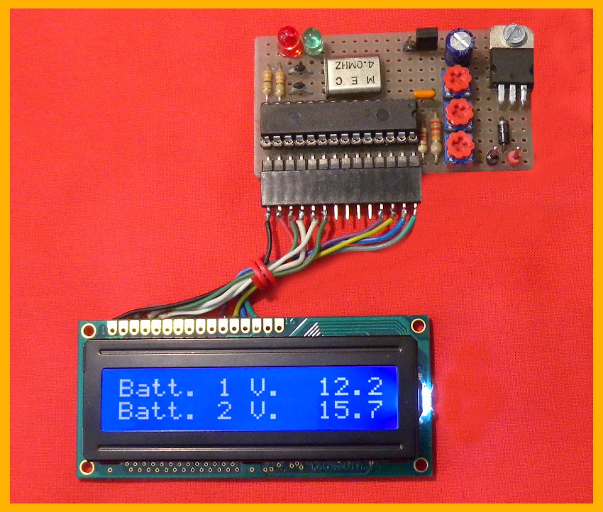
Project.. Voltmeter Ammeter LCD.... Battery charger |
 Description : The project as it is measures voltages up to 50.0 Volts and currents up to 6.9 Amperes after which it signals Over-Range. Therefore it can be used as an indicator tool in a power supply. However, I would like to underline that, naturally for those who have some experience with PIC assembler, the circuit lends itself as a basis for further developments. In fact we still have around eighty percent available of programmable memory as well as all PORTS B0/7. In the ReadTension/ReadCurrent routines we can therefore insert the necessary code to obtain the automated functions in the presence of certain voltage or current values. I tried to make the listing as linear as possible precisely to give the possibility to modify it as desired. The four instructions indicated as service routines are those that allow you to jump to the subroutine dedicated to the particular function. I hope it can also be useful on an educational level to understand the functioning of the Analog/Digital converter present in the PIC: in this regard I have made an identical base without input circuit . |
Indications for the CS resistor : it is a cut-out of a single-sided copper base measuring 3 mm x 35 mm, however not critical due to the presence of the adjustment trimmers. I limited the Over-Range current to 7 Amperes precisely for this component, in theory you can reach up to 50 Amperes by appropriately sizing the aforementioned component. |
 Logic for automating a battery charger : the proposed circuit that uses the project described above, with some modifications shown in the electrical diagram, serves to keep two 12 Volt batteries charged. When the voltage drops below 12.5 Volts the charger is inserted until the voltage rises to 14.5 Volts. The software is different and therefore you must download the Charger.zip file from the download . Logic for automating a battery charger : the proposed circuit that uses the project described above, with some modifications shown in the electrical diagram, serves to keep two 12 Volt batteries charged. When the voltage drops below 12.5 Volts the charger is inserted until the voltage rises to 14.5 Volts. The software is different and therefore you must download the Charger.zip file from the download .
|