
Description and characteristics :
Receives/transmits beacons for traffic in APRS. It displays the packet traffic on the 480 x 320 TFT display: the encoding/decoding part of the signal as well as the management of the display is entrusted to Arduino Mega, so there are only a few necessary components housed on the milleforo board at the side. The beacon transmission can occur with intervals of 2, 4 or 8 minutes, selectable via the jumpers on the board. The software part concerns the management of the various pages displayed on the display, while the encoding / decoding of the AX25 protocol is obtained through the LibrAPRS.h library and the various files attached and downloadable on Git_Hub. Naturally, the NMEA protocol is respected to be compatible with the program UI View. It was necessary to modify the device.h file to move the PORTD ports (used by the display) to PORTL which remained available. The signal input from the RTX is also now on PORT A7 while the original circuit used PORT A0 which is also used by the display. The vertical trimmer takes care of the offset voltage on the audio input and must be adjusted for 2.8 volts while the horizontal trimmer serves to regulate the intensity of the signal to be sent to the microphone input of the RTX .
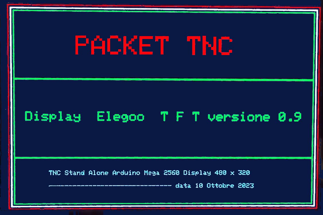 :::::::::
 ....Presentation screen........................................................................................................................Traffic screen APRS
Additional card :
the pin at the top left connects to the RTX and in particular GND, speaker, microphone, PTT (red sign). The pin at the top right connects the Arduino Mega with this sequence: PTT - pin 46, PL7 - pin 42, PL5 pin 44 (red mark). Bottom plug In 3.3 Volt, Out Aref, Out pin A7 (red mark). Plug on the right from the top: GND, pin 53 Led RX, pin 51 Led TX, pin 45 PL4, pin 43 PL6, pin 41 selects beacon interval 4 minutes, pin 39 as above for 8 minutes. The switch is used to switch from the view with the map to that with Packet traffic only. Added a 7808 with a small heatsink to power everything on 12 volts DC .
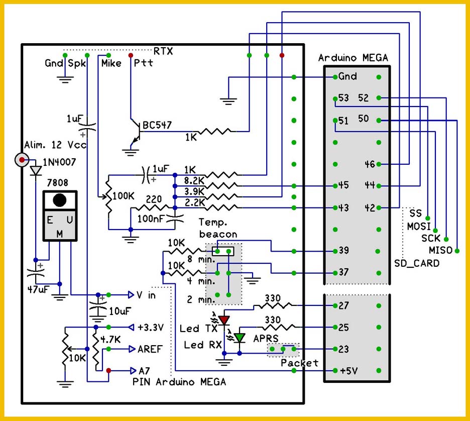 Elettrical scheme
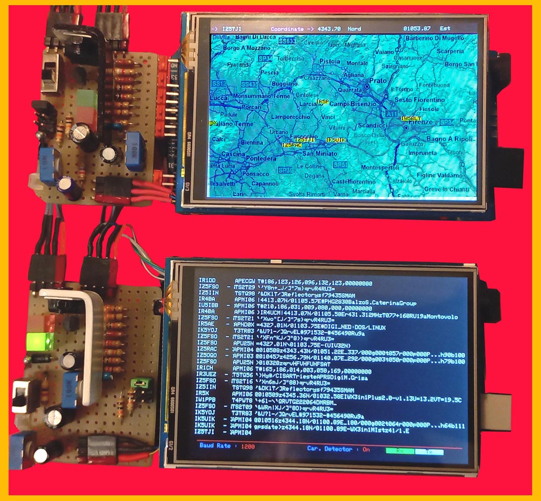 ...........
Latest version with map display : .........................................................
The reference of the coordinates on the map is obtained from the reception of the various beacons with the NMEA protocol. This version required the modification of the Sd2Card.h and Sd2PinMap.h libraries to be compatible with the Arduino Mega board as the original soft was created for Arduino Uno which however occupies all the available pins. The map is loaded from the S_Card with the 03.bmp file: these are the maps used at the time with the UI-View program, however reduced in this case to a part of Tuscany in order to still be able to read the various locations. The pins used at this point for the S_Card are the following: pin 50 = MISO pin 51 = MOSI pin 52 = SCK pin 53 = SS .
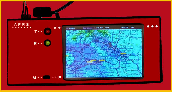 ....
....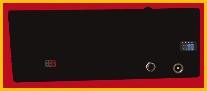 Definitive version : Upper panel with the Tx and Rx LEDs the switch to switch from viewing packet traffic to map mode and obviously the display. Rear panel starting from the left socket for programming the Arduino AT-MEGA from the outside then the power switch, power socket and just above the plug for connection with the transceiver.