
Bitx40 40 m band transceiver. with TFT Touch-Screen display
It repeats the same characteristics as the version with the graphic display: i.e. double VFO, possibility of operating in split, VFO selection for transmission, deactivable AGC and LSB or CW mode. The buttons have been eliminated, replaced by the touch-screen while the + 100 (Up) and - 100 (Down) buttons are shown on the microphone. The encoder button is used to move the cursor to modify the values indicated by the cursor itself.t repeats the same characteristics as the version with the graphic display: i.e. double VFO, possibility of operating in split, VFO s
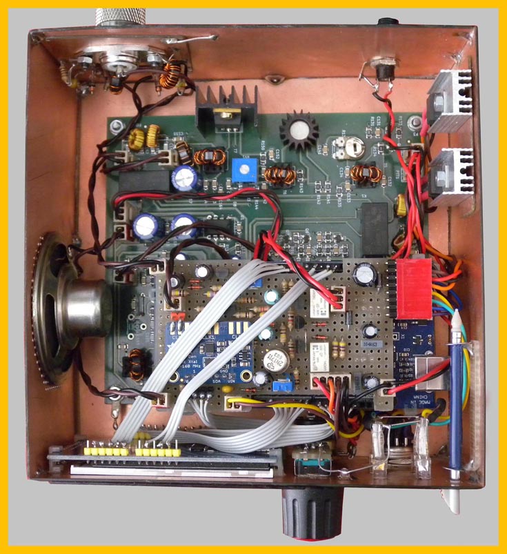
Photo below: component layout: above the millefori with the SI5351 frame, circuitry relating to the AGC and LSB - CW switching. Due to limited space, the CW note generator with the 555 and related components is mounted under the pseudo-SMD type millefori (the part under the SI5351 frame is free): in fact the intention was to use one of the PWM outputs available in the Arduino Mega but due to small delays introduced by the software, it was not possible for me. The Arduino Mega 2560 is still mounted underneath as a sandwich (you can see the connections relating to the display). Then finally the original Bitx40 frame. The mysterious object on the bottom right is the touch-screen pen. As seen in the photo, 7808 and 7805 must be dissipated.
 ............
![]()
...............................................
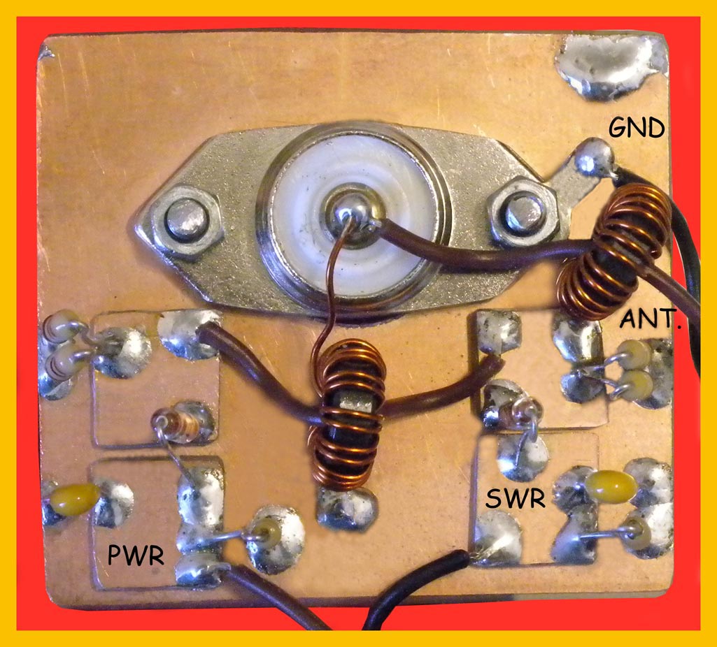
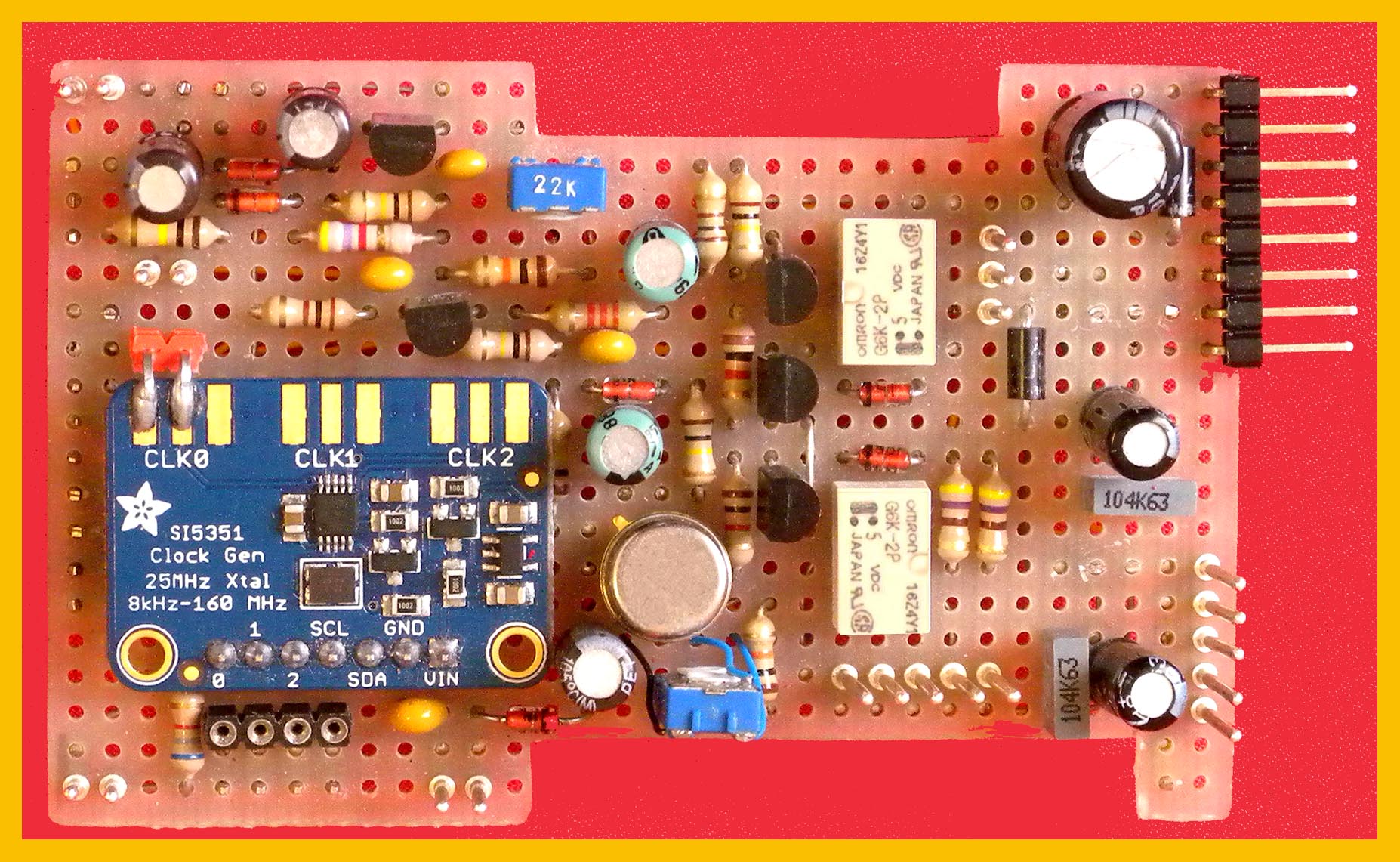 Detail of the circuit relating to the direct / reflected power meter proposed by ND6T Don Cantrell: Toroids used T37 / 43, the secondaries are wrapped with 20 spires of 0.5 mm wire enamelled while the primaries are simply isolated copper conductors and pass through the bulloids. On the right the circuit on the Millefori base: includes the power supply, the SI5351 frame, the circuit for the AGC the switches with the relays and the amplifier for the S-Meter.
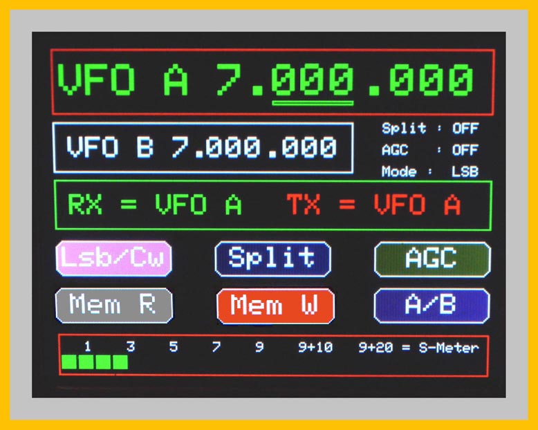 ........
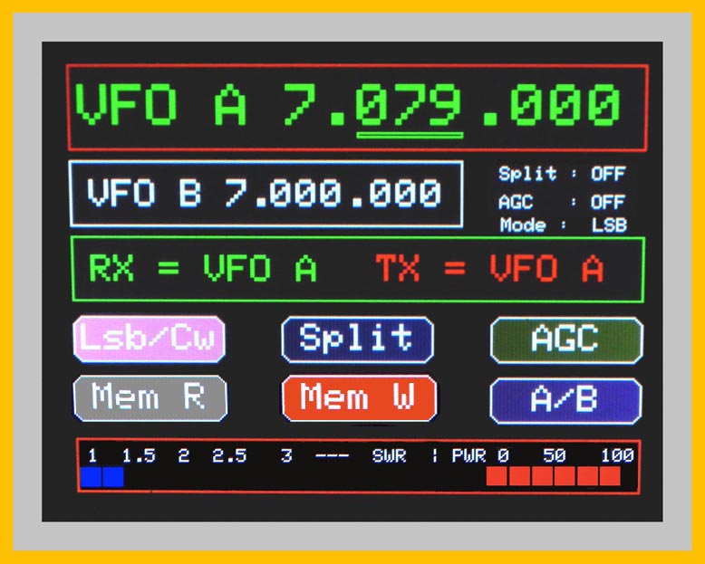 ............... Photo display: shows the VFO - A frequency, under the VFO -B frequency indication, then the indications if Split, AGC and Mode are inserted. The next line indicates when the split is switched on which VFO is switched on for reception and transmission. Then the buttons to select the various functions: in reception we have the indication of the S-Meter, while in transmission the SWR and the transmitted power are shown.
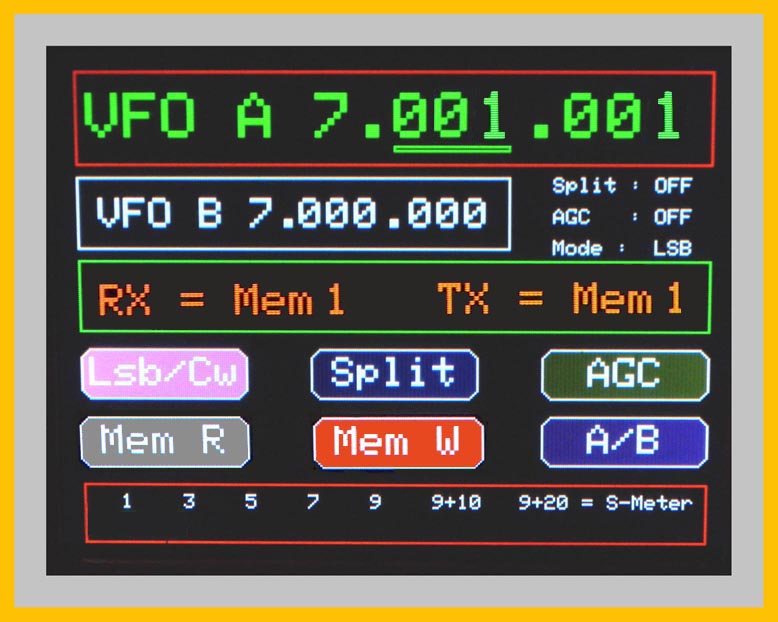 ...........
 .........Photo Display: reports the Freqenza del Vfo - A, under the indication of VFO -B frequency, then the indications if inserted the split, the AGC and the way. The next line indicates when inserted the split which VFO is inserted in reception and transmission. Then the buttons to select the various functions: in reception we have the indication of the S-METER, while the transmission is shown on the switch and the transmitted power.