Graphic display management and creations .... |
The purpose of this page is to clarify the management and therefore the use of the graphic display, which is not exactly an easy task. Let's start by downloading the datasheet of the Hitachi HDM64GS12 or AGM1264F or other equivalent displays as long as they have a 128 x 64 matrix. We see that in addition to the dimensions, electrical characteristics and other information, the following table is reported which should clarify how each individual pixel of the display is managed.
So once you have the display, the PIC and the necessary knowledge, it's a matter of writing some code to manage the display... well I've given up on it!! If we try to draw some vertical lines with some FOR loops we get by but if we then want to add some horizontal lines (without deleting the verticals) the problem becomes very complex. Luckily there is a loophole and it is called GLCD.C: it is a library written in C that takes care of interfacing the PIC with the display. Unfortunately, this file is covered by copyright and therefore not open source, but if you look around the Internet.... in fact you can find multiple versions and below I report two versions, the first with a more 'elegant' 5 x 7 character matrix and a 3 x 5 matrix with smaller characters:
Let's see how the library works: first of all I renamed them GLCD_35.C and GLCD_57.C to use them as desired. You can then call the various routines for the following functions: glcd_init(mode) : initializes the display mode ON OFF glcd_pixel(x,y,color) x or position. y pos. vert. color ON OFF ON turns on pixel OFF turns it off glcd_line(x1,y1,x2,y2,color) draws a line with coordinates x1,y1 starts and x2,y2 ends line ON and OFF writes or deletes glcd_text35(x,y,textptr ,color) writes or deletes text x and y writing start coordinates textptr string to write color ON OFF writes or deletes. As you can see, each function includes the ON and OFF option, which is absolutely essential because any change in writing or anything else on the display requires the old value to be deleted first, otherwise the writing will overlap glcd_fillScreen(color) turns on or off all the pixels of the screen glcd_circle (x,y,radius,fill,color), glcd _bar(x1,y1,x2,y2,width,color), glcd_rect(x1,y1,x2,y2,fill,color) less used Let's then move on to the practical implementations. The two proposed implementations refer to an ADC_Tester and a digital oscilloscope. Both use the same electrical diagram, therefore the same components only change the software to be downloaded into the PIC. In this regard, if anyone is interested, you can download the source and .hex files in the download section.. |
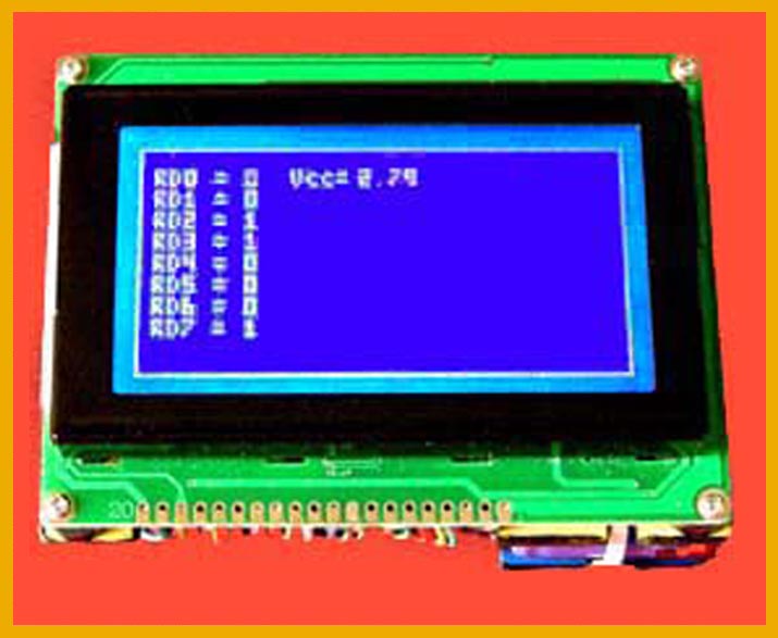
 As you can see, ADC_Tester displays the status of the output lines from the ADC0820 and the value of the input voltage. This is mainly a didactic implementation, however another eight inputs of the unused RA0-7 ports could be added. As you can see, ADC_Tester displays the status of the output lines from the ADC0820 and the value of the input voltage. This is mainly a didactic implementation, however another eight inputs of the unused RA0-7 ports could be added. |
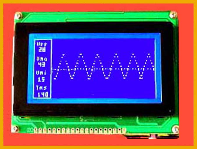
 Digital oscilloscape. This is the final project for which the display study is finalized. Project fully functional, but still in the pipeline to try to increase the bandwidth (for now limited to a few KHz despite the use of the ADC0820 external to the notoriously slow PIC) furthermore the synchronization with the input signal must be improved, as well as a input circuit to bring the maximum voltage to at least 50 Volt. Digital oscilloscape. This is the final project for which the display study is finalized. Project fully functional, but still in the pipeline to try to increase the bandwidth (for now limited to a few KHz despite the use of the ADC0820 external to the notoriously slow PIC) furthermore the synchronization with the input signal must be improved, as well as a input circuit to bring the maximum voltage to at least 50 Volt. |
|