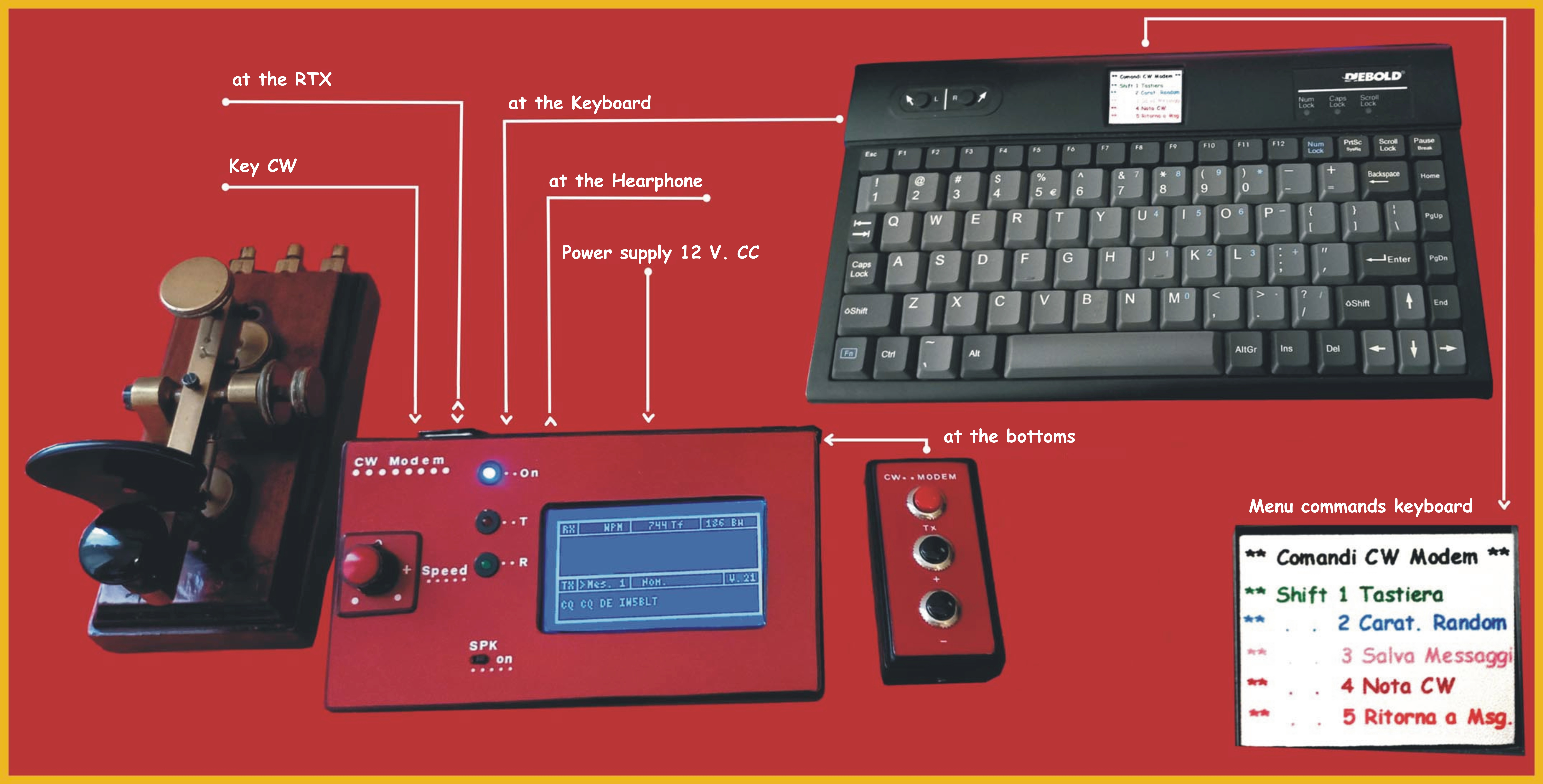
Complete project with the keyboard, the command with the three buttons and the CW key
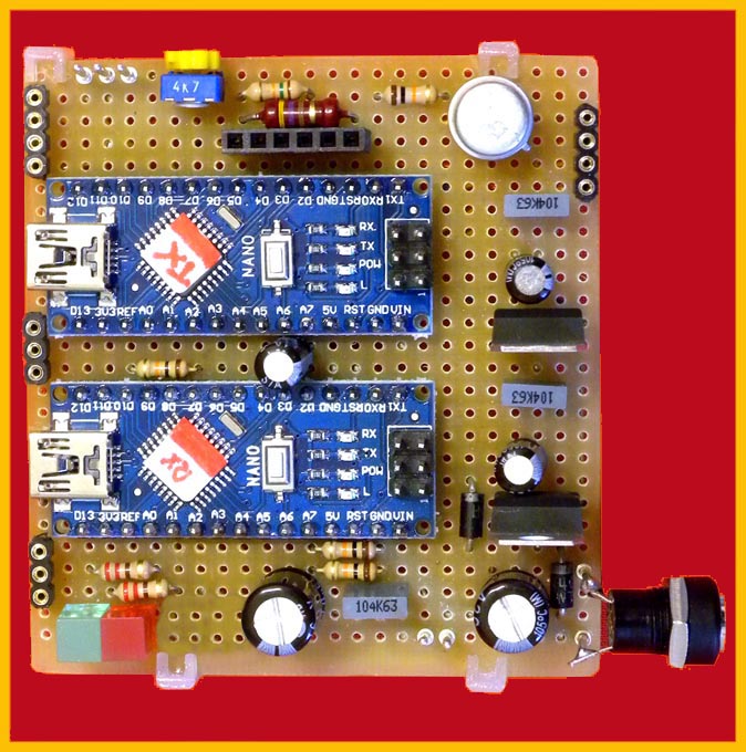
Component layout and project description :
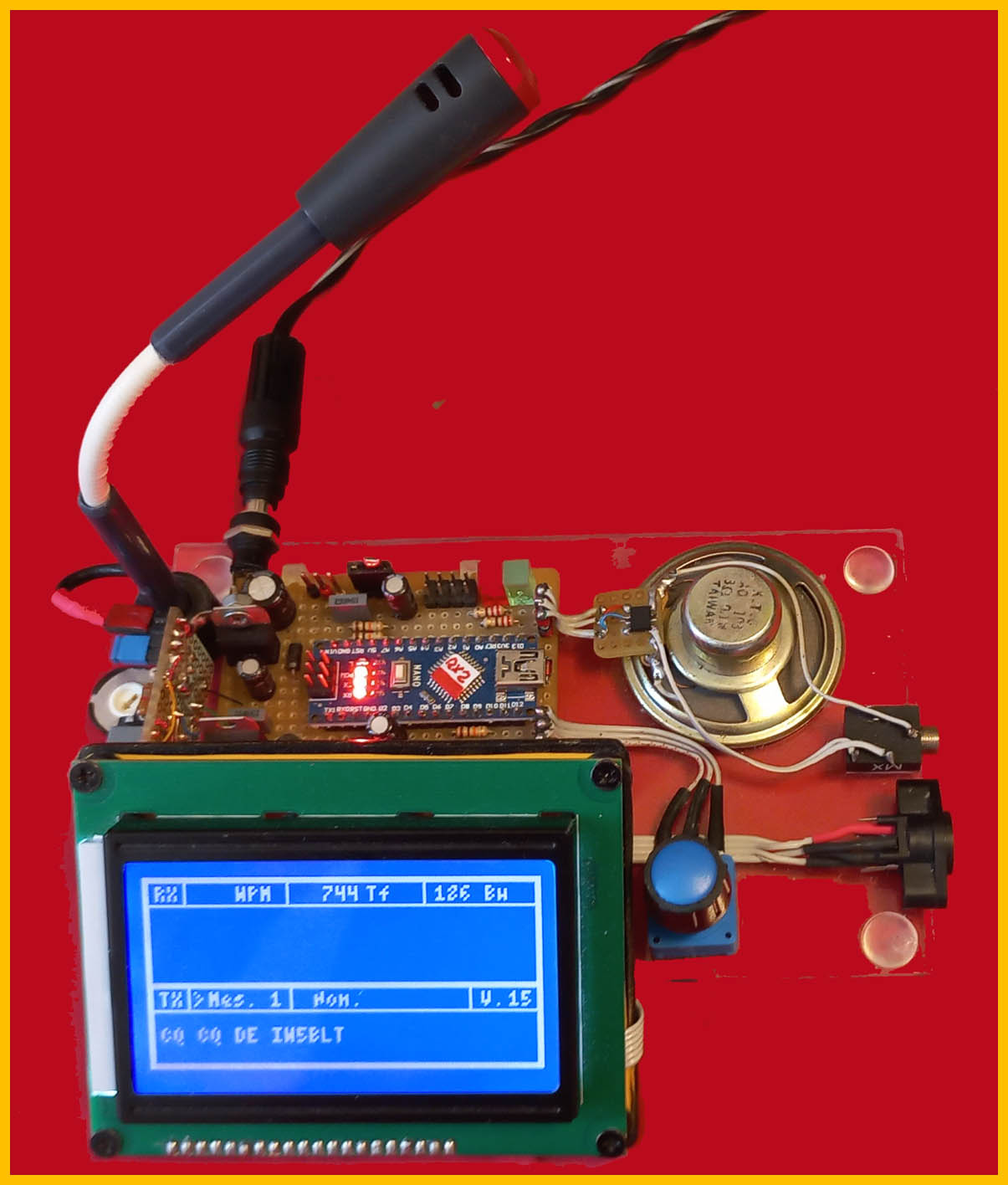
Modulator and demodulator for CW: as you can see, it was necessary to use two Arduino Nano boards, this is due to the fact that in order to use the graphic display and therefore visualize both the receiving and transmitting parts, it requires continuous refresh, distorting the timings necessary for the receiving party. The problem is solved by using two coupons which today can be found at very modest prices. Furthermore, it can also be seen that few other components, which are also cheap, are needed: the graphic display is the most important expense. Let's talk about the software: in the receiving part the Goertzel algorithm is used to demodulate the signal as happens more or less in all the programs I have had the opportunity to see. The transmitting part generates the signal to be transmitted, manages the display and interfaces the PS2 keyboard necessary to enter the correspondent's name, select the message to be transmitted, modify and store the messages. Speaking of which, there are 5 preset messages and the possibility of modifying them via the keyboard, furthermore by pressing the '*' key they will be stored in the EEprom. The purpose of the command with the three buttons is to eliminate the keyboard and can be convenient for use on a laptop: the three buttons serve: 'TX' transmits the displayed message, '+' increases the number. of the message, '-' decreases the n. of the message: obviously in this condition it will not be possible to enter the correspondent's name or modify the messages .
Evolution of the project :-
Version 1 . 0 : basic version with features that are also repeated in subsequent versions. Therefore the demodulator is present to receive and display CW traffic: in transmission it is based on the set messages, with the possibility of modifying them and saving them in the EEprom, as described elsewhere. Furthermore, the correspondent's name can be entered .-
Version 2 . 0 : it does not require any hardware modification, just program the Arduino Tx with this software version. Operating mode: with the 'Shift 1' keys you enter keyboard mode, while with 'Shift 2' you return to message mode. It can also be used for educational purposes, in fact by typing a single character or a group of characters you can listen to the notes generated while also adjusting the appropriate speed . Version 3 . 0 :in addition to the features listed previously I have included some useful functions for learning CW. Here a small hardware addition is required to be able to connect the CW button to pin A1 of the Arduino TX and the other side to ground as shown in the wiring diagram. In summary the possible functions are the following: 'Shift 1' key keyboard mode: every single character typed on the keyboard will be displayed and transmitted. 'Shift 2' key: pressing 'Enter' generates six random characters which plays into the speaker and then displays them. 'Shift 3' key saves the set messages on EEprom. 'Shift 4' key enables the CW key and generates the note heard in the speaker. 'Shift 5' key returns to message mode .
Useful information and visualization on the display :

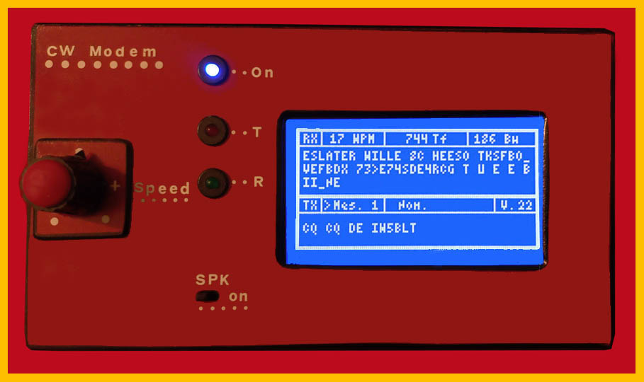 . Top.panel in addition of course to the display, the potentiometer that regulates the transmission speed and the three LEDs respectively 'On' blue 'Transmission' red 'Reception' green. Furthermore there is a switch to exclude the speaker.
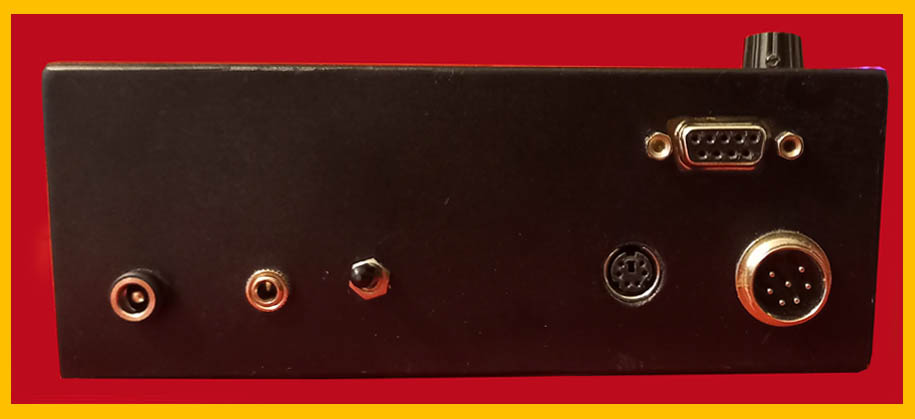
Back panel : from the left power socket, jack for the earphone, power switch, PS2 socket for the keyboard, at the top socket for the commands with the keys and then socket for the connection with the transceiver: it is also used to connect the CW key in since in this case the cable connecting the transceiver is no longer necessar .
........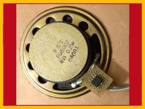 TDA7052 smd mounted directly on the speaker
Info & Biografie
Three prototypes have currently been built and are being beta tested by some willing radio amateurs. The files for programming the two Arduino Nanos are available in the download section: CCWW_Rx.cpp.hex file for programming the Arduino Nano Rx, CCWW_Tx.cpp.hex in the Arduino Nano Tx and the EEprom_XX file also in the Arduino Nano Tx: for programming I used Atmel Studio v 6.0 or v 7.0 and it is essential to program the memories first and only then the EEprom. Naturally, the name is not present in the EEprom and must be entered via the keyboard and then saved. Furthermore, since the program performs a check, it is essential that the EEprom is programmed with the appropriate values.
Biographies :
Arduino Nano documentation
Documentation relating to the Goertzel algorithm
.. -----------
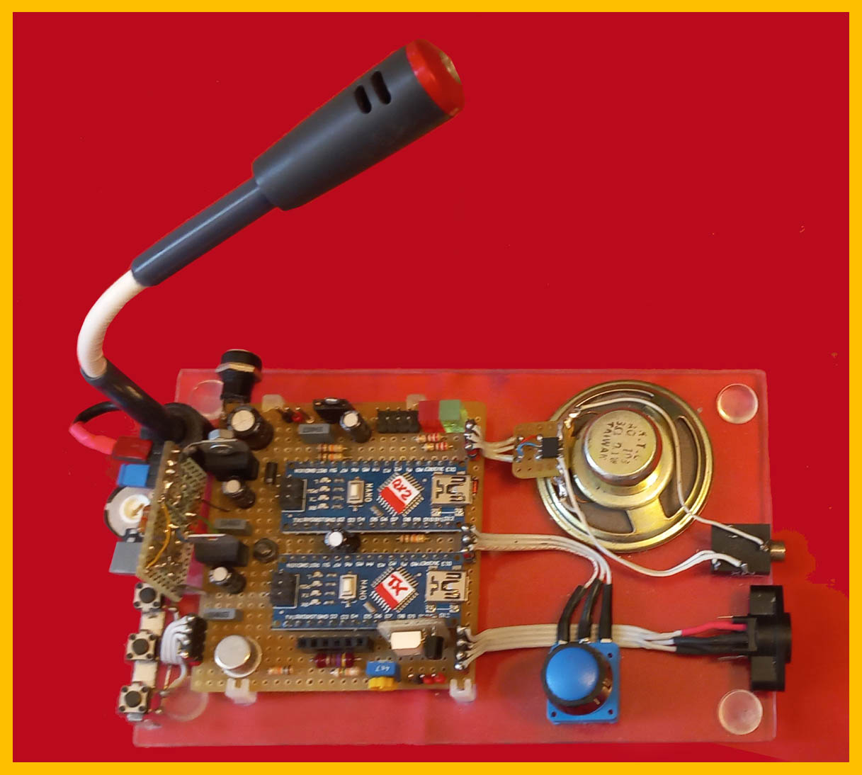
:::Trial version : in addition to the usual features, as can be seen in the photos, a microphone with relative amplifier (TL081) and associated circuitry has been inserted in order to receive the signal directly from the transceiver speaker and therefore no connection with the radio is necessary: naturally this is not possible transmit otherwise you must connect the appropriate cable to the radio. Furthermore, you must insert the earphone which excludes the speaker otherwise unwanted returns will be triggered.
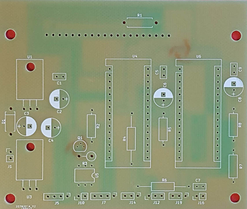 --------
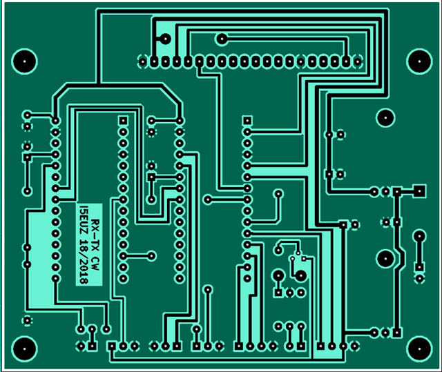
Printed circuit and component layout :
created by Vinicio I5EUZ: I would like to point out that it is the version with the keyer for connecting to the RTX. Furthermore, the TDA7052 is mounted directly on the speaker (see photo) .